What is a cable cleat?
Cable cleats are devices designed and tested to ensure the retention and support of cables, and have been used for many years all over the world. However, it was not until 2003 with the emergence of the standard EN 50368 being released, that any standard for cable cleats existed. This standard not only highlighted the retention and support that cable cleats provided to cables, but more importantly it highlighted the protection
of the cable management system and the potential risk to human life without the use of cable cleats. Prior to EN 50368 both cable and cable cleat manufacturers provided their own testing to their own standards.
This was then followed up with the publication of IEC 61914 in 2009 which further highlighted the importance of cable cleat products, and correct cable cleating.
IEC 61914:2009
‘cable cleat’ according to IEC 61914:2009 defined as a:
‘device designed to provide securing of cables when installed at intervals along the length of cables.’
‘Note: A cable cleat is provided with a means of attachment to a mounting surface but does not rely on an unspecified mounting surface for the retention of the cables. Examples of mounting surfaces that may be specified are ladder, tray, strut, or rail, wire and beam. Where declared, cable cleats provide resistances to electromechanical forces’
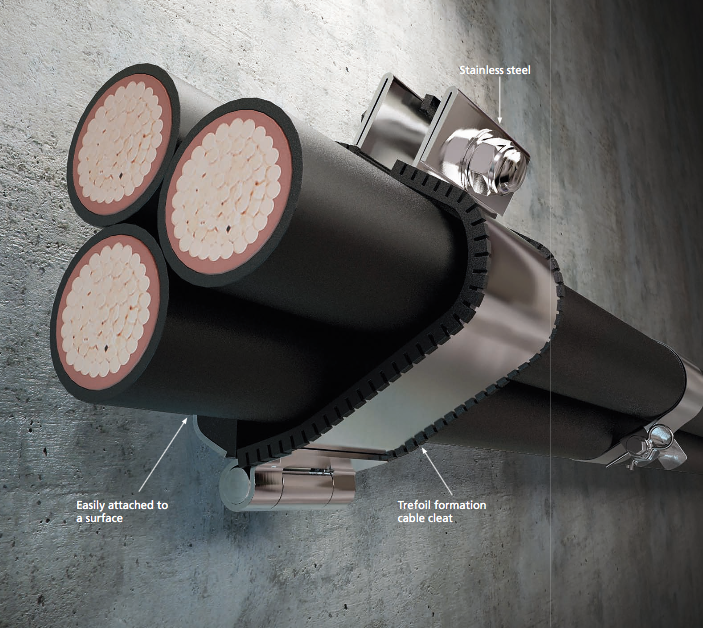
cable cleat
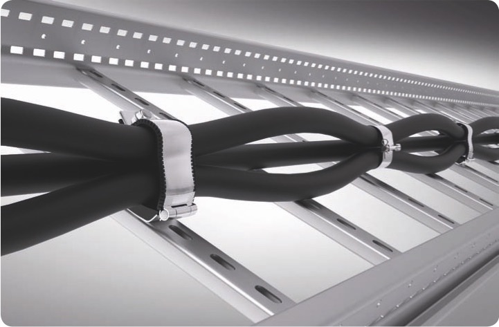
Intermediate restraint
‘intermediate restraint’ according to IEC 61914:2009 defined as:
‘cable retaining device to be used with cable cleats to hold the cables together in order to provide resistance to electromechanical forces. Intermediate restraints are not attached to the mounting surface’
- Reduce the mechanical load a cable may be exposed to due to electrical fault conditions.
Can I use a circuit breaker instead of cable cleats?
Although circuit breakers are capable of instantaneous protection, damage to the cables under fault conditions occurs within the first quarter cycle of the fault. Within this period of time the circuit breaker cannot open to suspend the fault, resulting in cable management system damage. A typical circuit breaker interrupts the fault after three cycles. Whilst this may protect the equipment, the cables however may have already been damaged within this short duration and depending on the size of the short circuit, need replacing.
The replacement of any cables comes at a high price as this not only includes the expensive cable costs themselves, but the labour time of decommissioning, the reinstallation of the cable management system. Not only this but the downtime of the operation must also be considered.
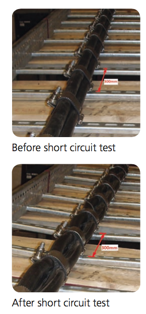
The latest standard for cable cleats IEC 61914:2009 lays down the standardised method for testing and certification of cable cleats to prove they can withstand one or more short circuit tests: 6.4.3 resistant to electromechanical forces, withstanding one short circuit, 6.4.4 resistant to electromechanical forces, withstanding more than one short circuit.
Cable cleat selection
Cable cleat selection takes into account numerous factors listed below, and ideally if CMP Products can be supplied with the following: cable construction – type, ratings and diameter, system design, support structure and environment; it will then be possible to assist you with further advice on the correct type of cable cleat, and also the cable cleat spacing requirements for your specific application.
Cable – What type of cable is being used?
Diameter – The overall diameter of the cable will allow CMP Products to not only size the correct cable cleat, but it will also be required for calculating the short circuit forces the cable cleat maybe subjected to under fault conditions.
Performance – Does the cable have any fire performance (FR), or Low Smoke & Fume or Zero Halogen (LSF / LS0H / LSZH) requirements that the cable cleat would also have to adhere to?
Cable type – Is the cable a single core or multicore cable? What voltage is the cable? Low voltage (LV), Medium voltage (MV), or High voltage (HV).
Design – Overview of the cable management system
Mechanical load – what will the cable cleat have to support?
All CMP cable cleats having been tested for both axial and lateral loads, this will ensure they will be capable of supporting the weight of the cables(s).
Short circuit rating – What kA peak fault or RMS?
What is the maximum peak fault (kA) the cable may be subjected to under short circuit conditions? Based upon the specified cable the short circuit rating can be calculated with use of the standard IEC 61914:2009 to give the maximum forces the cable cleat will need to be able to withstand during a short circuit fault.
Cable configuration – Flat form / parallel or trefoil formation?
The cable configuration of the system will define the type of cable cleat required; either a single cable cleat, a trefoil cable cleat, a quad cable cleat, or this may even indicate that a bespoke cable cleat may be required which CMP Products will design, test, and certify to suit the cable management system requirements of its client.
Cable run length – How many cable cleats are required?
Whilst the spacing requirements for cable cleats will be subject to cable formation, cable diameter, and short circuit rating, the overall cable run length will give the correct number of cable cleats required for the installation. Cable runs that turn through 90° must also be noted as the cable cleat spacing will be reduced throughout these bends.
Expansion
Single core cables expand and contract more due to temperature changes
than multicore cables. If the cable is constrained, considerable forces can be transferred to the supporting structure. To allow for this, single core cables
are generally “snaked” making slight loops to take up the expansion and contraction. It is also usual to allow some of the cable cleats to move freely and not restrain all cable cleats.
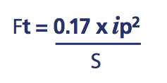
Cable cleats – Short Circuit Calculations
Installation